Why Choose Pin Header Sockets for Your Projects?
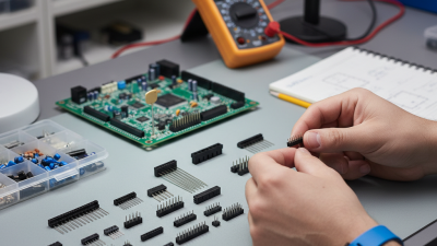
A Pin Header Socket can make an electronic project easier to assemble, test, and revise. It creates a removable connection between a circuit board and compatible pin headers. That matters when a sensor, module, or small controller may need replacement. No desoldering required. During prototyping, this flexibility can save time and reduce stress on delicate board pads. A socket can also help keep connections organized, especially when several modules sit close together. Still, it is not an automatic upgrade. Added height and contact resistance may matter in compact or power-sensitive designs.
This article explores where socketed connections work well and what to check before choosing one. Pin spacing, row count, mounting style, and rated current should match the header and application. For example, a socket that fits a common 2.54 mm header may not suit a low-profile enclosure. On a vibrating device, a removable connection may also need secure retention and careful mechanical support. Check the manufacturer’s datasheet rather than relying on appearance alone. A socket can simplify maintenance, but it may introduce another point of failure. That trade-off is easy to overlook. The right choice depends on how often parts change, how much space is available, and how reliable the connection must be. Even a simple prototype benefits from checking fit and alignment before power is applied.
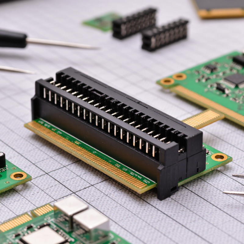
Pin Header Sockets Defined: Common 2.54 mm and 1.27 mm Pitch Formats
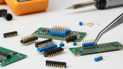
Pin header sockets use a center-to-center spacing called pitch. The common formats are 2.54 mm and 1.27 mm. These equal 0.100 inch and 0.050 inch, respectively. The 2.54 mm format leaves more room for a soldering iron, test probe, or jumper wire. The 1.27 mm format packs connections more tightly, which can help when board space is limited. Fit matters.
IEC 60603-13 is a useful reference for printed-board connector interfaces, while IPC-2221B addresses broader PCB design constraints. Neither pitch alone guarantees electrical suitability. Check the socket drawing, mating-pin dimensions, current rating, and board footprint before ordering. A compact 1.27 mm socket may save area, but alignment becomes less forgiving during assembly. I would also leave enough clearance to reach adjacent pins with a probe. That detail is easy to miss. The smaller format is not automatically the better choice; the right pitch depends on assembly method, access, and the actual mating component.
Contact Performance: Verify Ratings and Test Methods in IEC 60512
Why Choose Pin Header Sockets for Your Projects?
Pin header sockets make prototypes easier to inspect, replace, and rework. Yet a snug fit alone does not prove reliable contact. Check the socket’s rated current and voltage against your circuit, then review how its contact performance was tested. IEC 60512 provides test methods for connectors; it does not set one universal pass limit for every socket. Look for the relevant test number, sample configuration, and acceptance criteria in the technical documentation.
Contact resistance is a useful starting point. A four-wire measurement can reduce lead resistance in the reading, especially when contact values are low. For loaded assemblies, measure temperature rise at the intended current and note the test conditions. Wire gauge, board layout, airflow, and mating cycles can all affect results. A socket that passes a bench test may behave differently inside a warm enclosure. That deserves a second look.
Tips: Compare results only when methods and conditions match. Confirm whether the current rating applies to one contact or the complete assembly. Ask for durability test evidence if the socket will be unplugged often. Record insertion force, contact resistance, and temperature during your own checks. Small differences matter. Test the actual mating pin, too; nominal dimensions do not always tell the whole story.
Why Choose Pin Header Sockets? Contact Performance and IEC 60512
Illustrative voltage drop across a 10 mΩ contact path, calculated using V = I × R. The current values are example points, not IEC 60512 test requirements or socket ratings.
Use the applicable IEC 60512 test method—such as IEC 60512-2-1 for the millivolt-level contact-resistance method—and compare measured results with the socket’s product specification. IEC 60512 does not set one universal contact-resistance limit for all sockets.
PCB Layout: Apply IPC-2221 Clearance Rules to Socket Connections
Why Choose Pin Header Sockets for Your Projects?
A pin header socket makes a connection removable, but its footprint still needs careful spacing. IPC-2221 provides guidance for electrical clearance and creepage based on factors such as voltage and the board environment. Clearance is the shortest distance through air between conductors. Creepage follows the board surface. They are not interchangeable.
Check the socket’s actual pin pitch against the clearance your design requires. A fine-pitch socket may leave less room than expected once solder fillets spread around its pins. Keep nearby copper, exposed pads, and board edges in view. Small gaps matter. I have seen a layout look roomy on screen, then feel crowded after the socket and solder joints were added. That is easy to miss.
Use the applicable IPC-2221 guidance and your project’s requirements to set spacing; do not assume one clearance fits every voltage or environment. Check the manufacturer’s footprint, then review the finished layout for narrow points between pads and neighboring conductors. Consider coating, contamination, and assembly tolerances where relevant. A design rule check helps, but it may not catch every physical constraint. I still recheck the socket area at full scale. The first footprint is not always the right one.
Selection Criteria: Compare Plating, Contact Ratings, and Mating Cycles
Why Choose Pin Header Sockets for Your Projects?
Selection Criteria: Compare Plating, Contact Ratings, and Mating Cycles
Pin header sockets allow boards and modules to connect without soldering every interface permanently. That makes inspection and replacement easier during prototyping or maintenance. Selection still matters. A bright finish alone does not tell you how well a socket will perform in your environment. Compare the stated plating material and thickness, especially if humidity or frequent handling is expected. Gold plating can resist oxidation, but its value depends on the application and specified thickness.
Tips: Check the datasheet, not just the product photo. Match the socket’s contact rating to your circuit’s current and voltage, with suitable design margin. A socket rated for a small signal may not suit a power path.
Also review the rated mating cycles, which indicate how many insertion and removal operations the contact is designed to withstand. The actual service life can vary with alignment, insertion force, contamination, and handling. A tight enclosure may make straight, even insertion difficult; that detail is easy to overlook. For frequently swapped modules, prioritize cycle ratings and mechanical fit. For a fixed connection, those features may matter less than contact stability and board layout. Compare specifications under similar test conditions, since ratings are not always measured the same way.
Project Applications: Use Socketed Headers for Prototyping and Modular Boards
Socketed pin headers make prototypes easier to revise without repeatedly heating and removing components. They are useful when a small controller, sensor, or display may change during testing. A module can be unplugged, inspected, and replaced while the main board stays wired. That saves time at the bench. It also reduces wear on solder pads.
For a modular board, sockets create clear connection points between functional sections. A motor-control circuit, for example, can sit on a removable board beside the processor section. Keep the pin layout consistent, and later revisions become easier to compare. Marking power, ground, and signal positions on the board helps prevent rushed wiring mistakes. Check the pin pitch and insertion depth before ordering; a connector that looks right may not fit the chosen module.
There is a trade-off. Sockets add height and can loosen after frequent handling, especially in portable builds. They also introduce extra contact points, so they are not ideal for every final product. During prototyping, though, the flexibility is often worth the space. I would still test the assembled board through repeated insertions; one quick fit check is not enough.

 Email
 WeChat