Top High Frequency Connector Types for Global Buyers
High-frequency connectors sit at the meeting point of signal integrity, mechanical fit, and supply-chain reliability. Ericsson’s November 2024 Mobility Report forecasts 6.3 billion 5G subscriptions by 2030, increasing demand for dependable RF connections across networks and devices. That growth does not make every connector suitable for every application. A compact board connector, an SMA interface, and a rugged N-type connector solve different problems.
For buyers searching “High Frequeency Connecotor,” comparing connector families is a practical starting point. Common options include SMA, N-type, BNC, MMCX, and high-speed board-to-board designs. Each has trade-offs in size, operating frequency, mating durability, and installation needs. Check impedance, insertion loss, return loss or VSWR, shielding, and the cable or PCB interface. A datasheet is useful. It is not the whole story.
The global connector market provides useful context, though it is broader than high-frequency products alone. Grand View Research estimated the connector market at about US$84 billion in 2023 and projected continued growth through 2030. That figure should not be read as an RF-connector market estimate. For global sourcing, buyers should also confirm test methods, material traceability, and performance across the intended frequency band. A connector can look perfect on paper. Real assemblies may behave differently. This guide compares the main types and the selection details that deserve closer review.
Understanding High-Frequency Connectors and Their Core Design
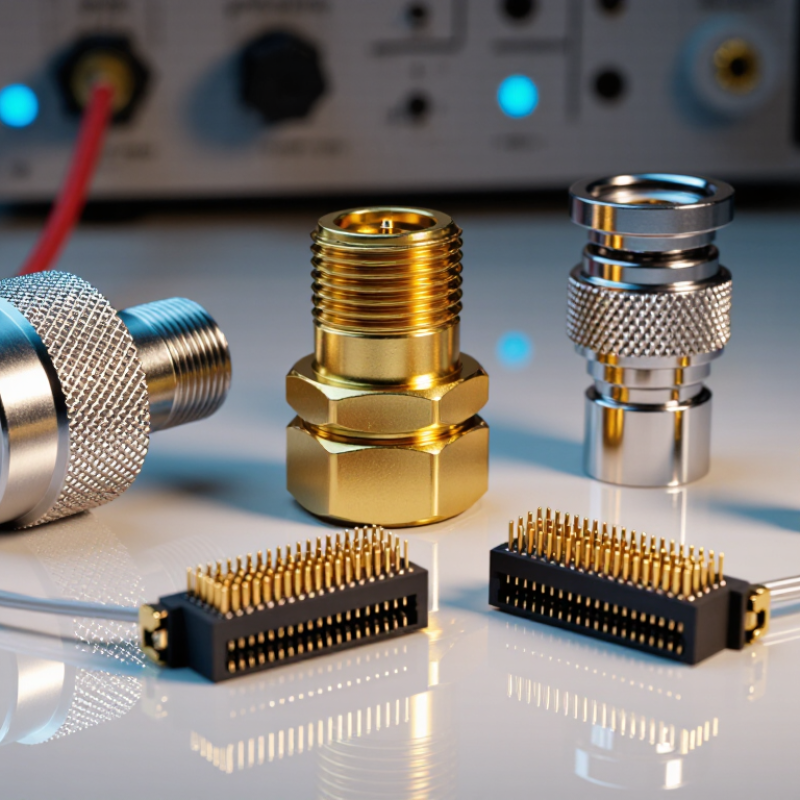
High-frequency connectors carry fast electrical signals between boards, cables, and test equipment. Their core design is about controlling the signal path, not simply adding more contacts. A small change in pin spacing or dielectric material can alter impedance and increase reflections. These effects may appear as eye closure, data errors, or heat at the interface. The details matter.
IEEE 802.3ck specifies 100-gigabit-per-second Ethernet lanes using 53.125-gigabaud PAM4 signaling, placing the Nyquist frequency near 26.6 GHz. That is a demanding environment. Connector designers manage impedance, insertion loss, return loss, and crosstalk through carefully shaped contacts, stable dielectric spacing, and continuous shielding. A connector’s rated frequency alone does not guarantee a reliable channel; the cable, board launch, and mating interface all contribute. Engineers should assess the complete path with suitable high-frequency measurements, not rely on a catalog number. Even good models can miss real assembly variation. A useful design review asks where the signal changes geometry, and whether those transitions have been measured under realistic conditions.
Common Coaxial Connector Types and Frequency Ranges
Common coaxial connector types cover very different frequency ranges. BNC connectors are commonly rated to about 4 GHz, while TNC and N-type designs often reach roughly 11 GHz. Exact limits depend on the connector version and test conditions. SMA connectors are widely used up to 18 GHz; precision versions may support higher frequencies. For millimeter-wave work, 2.92 mm connectors can reach 40 GHz, 2.4 mm about 50 GHz, 1.85 mm about 67 GHz, and 1.0 mm up to 110 GHz.
These figures are useful starting points, not guarantees for a complete cable assembly. The cable, adapter, connector wear, and installation can all affect measured performance. A connector rated for 40 GHz does not make an ordinary cable behave well at 40 GHz. Small gaps or a poorly aligned mating face can increase reflections. A frequency chart looks tidy, but real setups are less tidy; checking the full assembly’s data sheet and return-loss curve is more dependable than choosing by connector name alone.
Tips: Match impedance, frequency rating, and cable type. Keep mating surfaces clean, and avoid unnecessary adapters. If the system operates near a connector’s stated limit, allow margin and verify it with a suitable measurement.
Board-Level and Precision High-Frequency Connector Families
Board-level high-frequency connector families solve a difficult transition: moving signals from a compact circuit board into test equipment or another module. Surface-mount coaxial launches and board-to-board interfaces are common choices. Some designs use SMP or SMPM interfaces for dense, blind-mate assemblies; precision 2.92 mm and 2.4 mm interfaces suit measurement paths requiring tighter control. Small details matter. A short launch, uneven ground vias, or excess solder can disturb impedance and increase reflections. The connector alone cannot guarantee performance.
Demand is rising with wireless infrastructure. GSMA’s The Mobile Economy 2025 projects 5.5 billion 5G connections worldwide by 2030. That growth makes repeatable board transitions more important, but the forecast does not prescribe a connector family. Engineers should check the complete signal path, including PCB material, stack-up, connector mounting, and mating cycles. IEC 61169 provides a standards framework for RF connector interfaces, while specific frequency limits remain design-dependent. A catalog limit can mislead. It may describe a connector under ideal test conditions, not a populated board. I would verify insertion loss and return loss on the actual layout; this step is easy to underestimate.
Key Electrical and Mechanical Performance Characteristics
High-frequency connector performance begins with impedance matching. Many RF systems use 50-ohm interfaces, but confirm the equipment specification before ordering. A mismatch can increase reflections and weaken the signal. Check the rated frequency range, insertion loss, and return loss for the complete connector assembly, not just the connector body. Small details matter.
Connector families suit different tasks. BNC connectors offer quick bayonet coupling, while N-type and TNC designs use threaded connections that resist loosening. SMA and 2.92 mm connectors support compact, higher-frequency assemblies, but their ratings vary by construction. A datasheet’s maximum frequency is not a guarantee of low loss across every cable, adapter, and mating pair. Measure the assembled path when signal margin is tight.
Mechanical performance deserves equal attention. Look for secure coupling, stable contact pressure, and a housing that fits the panel or cable without strain. In field installations, vibration and repeated mating can affect contact quality. Use the specified torque where applicable, and inspect threads and center contacts for wear. Fit matters. I have seen selection tables simplify comparisons, but real installation conditions are easy to underestimate; cable bend radius and access for a wrench can change what works.
Top High Frequency Connector Types for Global Buyers
Representative nominal upper frequency limits for common 50-ohm coaxial RF connector interfaces.
Smaller precision interfaces generally support higher frequencies. These figures are representative interface limits, not guaranteed system performance; the connector design, cable, assembly, and test conditions also affect usable bandwidth.
How Global Buyers Compare Connector Specifications and Standards
Global buyers comparing high-frequency connectors should start with the operating band, not a headline maximum frequency.
A connector rated to 40 GHz may perform differently once cables, adapters, and board launches enter the measurement path. Check characteristic impedance, insertion loss, return loss, and VSWR across the full band. Small differences matter. Ask whether values are typical or guaranteed limits, and note the test method, calibration plane, and mating condition. Two datasheets may quote the same frequency but use different fixtures, so their figures are not automatically comparable.
Standards create a common language, but they do not remove every ambiguity. Compare interface dimensions and tolerances against the applicable IEC or other recognized specification. Then confirm how each supplier verifies mechanical fit, durability, and environmental performance. Review plating, contact material, operating temperature, vibration, and mating-cycle data when the application demands them. For a compact radar module, a slightly longer interface can complicate enclosure clearance, even when its RF figures look excellent. Request test reports for the exact configuration, including any adapters. This step is easy to miss. Confirm compatible mating parts, too. A neat comparison table is not proof; test a representative assembly where possible. Real setups can be less tidy.

 Email
 WeChat