Leave Your Message

What Is a High Frequency Connector Used For?

A high-frequency connector carries radio-frequency and microwave signals between components while helping preserve their quality. You may find one linking an antenna to a radio, a cable to a test instrument, or modules inside a communications system. The connector looks small. Its job is not.

At higher frequencies, tiny design details matter. Impedance, shielding, contact geometry, and cable compatibility can affect reflections, signal loss, and interference. A connector that fits physically may still perform poorly if its electrical specifications do not match the system. Engineers therefore check the rated frequency range and measurements such as insertion loss and voltage standing wave ratio. They also consider repeated mating, vibration, and the installation environment. A loose interface can spoil a careful measurement.

The term “High Frequeency Connecotor” may appear in searches, but product decisions should rely on verified datasheets and manufacturer guidance. Common connector families serve different frequency ranges and practical needs; no single type suits every application. For example, a laboratory test setup may prioritize repeatable measurements, while an antenna connection may require secure mounting and weather protection. Real-world performance also depends on the cable, adapters, and assembly quality—not just the connector itself. That point is easy to overlook. This guide explains what high-frequency connectors do, where they are used, and which specifications help identify an appropriate option. It also recognizes a limit: published ratings describe defined test conditions, not every installation. Check the complete signal path before choosing.
What Is a High Frequency Connector Used For?

What Defines a High-Frequency Connector?

A high-frequency connector is not defined by its metal shell or a “GHz” label alone. It is an RF interface designed to preserve a signal’s electrical behavior between a cable, circuit board, or instrument. Key traits include controlled impedance, low reflection, low insertion loss, and shielding against unwanted coupling. Small details matter. A slightly off-center pin or uneven contact can disturb impedance and create a measurable mismatch. The usable frequency range depends on the entire connection, including the cable, board launch, and assembly quality—not just the connector.

IEEE Std 287-2007 specifies precision coaxial connector interfaces. Its limits include 18 GHz for 7 mm connectors and 110 GHz for 1 mm connectors. These figures show how interface geometry relates to frequency capability; they do not guarantee performance in every setup. Engineers commonly check return loss and insertion loss with vector network analyzer measurements. A spec sheet can make results look cleaner than real assemblies are, so cable transitions and tolerances deserve a second look.

How Does a High-Frequency Connector Transmit Signals?

A high-frequency connector carries radio-frequency or microwave signals between a cable and a device, such as an antenna, test instrument, or circuit board. It does more than hold two parts together. Its internal shape helps preserve the signal as it crosses the connection.

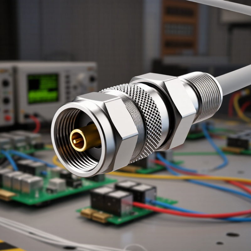
A coaxial connector guides the signal along a center conductor, surrounded by an insulating dielectric and an outer conductive shield. The center conductor carries the signal; the outer conductor provides a return path and helps limit electromagnetic interference. Their spacing and shape create a characteristic impedance, often 50 ohms in RF systems. That geometry matters.

At high frequencies, signals can reflect when they encounter a sudden change in impedance. A poor fit, damaged contact, or unsuitable connector may increase those reflections and weaken the signal reaching the next component. Small gaps count. Connector specifications therefore include operating frequency, impedance, and insertion loss, but real performance also depends on the cable, installation, and mating surfaces.

In a lab, technicians may check a connection with a vector network analyzer to measure reflected and transmitted energy. Even then, readings can shift if the cable moves or the connector is not fully seated. A connector is only one part of the signal path, and blaming it alone can miss the actual problem.

Where Are High-Frequency Connectors Commonly Used?

High-frequency connectors are used wherever radio-frequency signals must travel with controlled loss and impedance. They commonly link antennas, transmitters, receivers, and test equipment. In cellular networks, for example, short coaxial jumpers connect radio units to antennas on rooftop masts or tower panels. The Ericsson Mobility Report, June 2024, forecast 5.6 billion 5G subscriptions worldwide by the end of 2029. That expansion means more radio infrastructure, though it does not mean every connection needs the same connector.

They also appear in satellite ground stations, microwave backhaul, radar systems, and aerospace communication equipment. A dish feed may connect to a low-noise receiver through a carefully shielded cable; radar assemblies need connections that remain stable under vibration and temperature changes. The Satellite Industry Association’s 2024 State of the Satellite Industry Report estimated global satellite-industry revenue at $285.3 billion in 2023. This figure describes the broader industry, not connector sales, but it shows the scale of systems that rely on dependable RF links.

High-frequency connectors are common in engineering labs, too. Technicians attach them to spectrum analyzers, signal generators, and network analyzers when measuring cables or antenna performance. Fit matters. A loose connection, damaged center pin, or poorly matched impedance can distort a reading. One detail is easy to overlook: frequency rating alone does not guarantee suitability. Cable length, shielding, handling, and the actual operating environment matter just as much.

Which Performance Factors Affect Connector Suitability?

A high-frequency connector is suitable only when its performance matches the complete signal path, not just its advertised frequency limit. A connector rated near the top of its range may still introduce excessive loss there. Match its impedance to the cable and equipment; 50 ohms is common in RF systems. Return loss and VSWR indicate mismatch, while insertion loss measures signal energy lost through the connection. Check test data across the operating band. Small details matter. Even a short adapter can affect results.

Power handling matters when signals run continuously or in pulses, because a poor contact can generate heat. Shielding helps limit leakage and interference from nearby equipment. Contact geometry, plating, and connector wear can also affect repeatability, especially after frequent mating. Consider the cable type, bend radius, and installation space; a connector that performs well on a bench may be awkward or unreliable in a cramped enclosure. Temperature and vibration deserve attention, too. A tidy assembly is not always a good assembly. It is easy to overlook cable strain, yet movement can loosen a connection and change measured performance. Read specifications against real operating conditions, not just a single headline number.

What Is a High Frequency Connector Used For? Which Performance Factors Affect Connector Suitability?

Use or Performance Factor Relevant Data or Consideration Why It Affects Suitability
Wireless communications High frequency connectors join antennas, radio units, filters, and coaxial cables in cellular, Wi-Fi, and point-to-point radio systems. The connector must cover the system’s operating band and maintain a stable, low-loss signal through the connection.
Test and measurement Coaxial connectors link signal generators, spectrum analyzers, network analyzers, test cables, and devices under test. Repeatable connections and suitable impedance are important for reliable measurements, especially at microwave frequencies.
Radar, satellite, and microwave systems Connectors carry RF or microwave signals between transmitters, receivers, antennas, and associated equipment. Frequency range, power handling, environmental sealing, and mechanical stability must suit the equipment and operating conditions.
Operating frequency Common coaxial interface families have different typical upper frequency limits: N-type, around 11 GHz; SMA, around 18 GHz; 3.5 mm, around 26.5 GHz; 2.92 mm, around 40 GHz; 2.4 mm, around 50 GHz; and 1.85 mm, around 67 GHz. Choose an interface rated above the highest signal frequency. The usable limit depends on the specific connector, cable assembly, and mating components.
Impedance match and VSWR Many RF systems use a nominal 50-ohm impedance. Voltage standing wave ratio (VSWR) describes impedance mismatch; a lower VSWR generally means less reflected power. Impedance mismatches can cause reflections, measurement errors, and reduced power transfer. The connector should match the system impedance.
Insertion loss Insertion loss is the signal power lost when a connector or cable assembly is added to a path. Loss generally increases with frequency and can also depend on contact condition and assembly quality. Low-loss designs help preserve signal level, particularly in long cable runs and high-frequency links.
Power handling Power capability depends on frequency, connector geometry, cooling, ambient conditions, and the risk of voltage breakdown. Check the specified power rating at the intended frequency and operating conditions; a rating at a lower frequency may not apply at a higher one.
Contact durability and mating cycles Repeated mating and unmating can wear contacts and affect connection consistency. Precision interfaces may require careful handling and correct mating procedures. For frequently used test setups, durability and repeatable electrical performance can be as important as maximum frequency.
Environmental resistance Temperature range, moisture protection, vibration resistance, and corrosion resistance vary by connector design and sealing method. Outdoor, vehicle, and industrial installations need connectors rated for the actual environment, not only the electrical frequency.
Mechanical fit and cable compatibility Connector gender, coupling style, size, cable type, and termination method must be compatible with the equipment and cable assembly. A mechanically compatible connection helps prevent damage, poor contact, and unintended changes in RF performance.

Note: Frequency limits shown are typical interface-level guide values, not guarantees for every product. Always confirm the specified operating frequency, impedance, VSWR or return loss, insertion loss, power rating, and environmental ratings for the complete connector assembly.

How Do You Select the Right High-Frequency Connector?

Selecting a high-frequency connector starts with the system’s operating band, not its advertised maximum. Check the connector and cable assembly together; a strong connector cannot compensate for a lossy cable. Compare impedance, insertion loss, and return loss across the frequencies you will actually use. A 50-ohm system, for example, needs a 50-ohm connector to limit reflections. Small mismatches matter. The IEC 61169 series provides relevant specifications for radio-frequency connectors, but the exact part’s test data still deserves a close look.

Next, match the interface to power, space, and handling conditions. Check peak and average power, voltage, temperature range, vibration exposure, and expected mating cycles. A compact board connector may suit a crowded instrument, while a threaded type may better tolerate repeated connection. Confirm the cable diameter and termination method, too. I have seen selection sheets omit the assembly details; that is an easy gap to miss.

Deployment context matters. GSMA’s 2024 Mobile Economy report projects 5.5 billion 5G connections by 2030, increasing the need for dependable RF links across diverse equipment. That figure does not specify connector demand, but it underscores why repeatable performance matters. Ask for measured performance over the full band, including return loss, and verify the result on the completed assembly. A datasheet is not the whole system. For prototypes, inspect the connector after mating and test again after cable movement; small changes can reveal a weak termination.

High-Frequency Connectors: Frequency and Wavelength

High-frequency connectors carry RF and microwave signals in applications such as antennas, test equipment, and communications systems. This chart shows the free-space wavelength at selected frequencies, calculated using the speed of light (299,792,458 m/s).

How to select: Choose a connector rated for your operating frequency, then check impedance (commonly 50 Ω for RF), return loss or VSWR, power handling, and mechanical compatibility. Wavelength values provide context; actual connector frequency limits depend on the specific design and installation.