Leave Your Message

What Is a High Frequency Connector Used For?

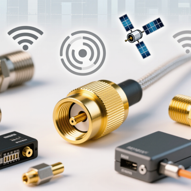
A High Frequeency Connecotor is used to carry high-frequency electrical signals between devices while helping preserve signal quality. In practice, it may link an antenna to a radio, connect a spectrum analyzer to a test cable, or join modules inside communication equipment. These connections appear in wireless networks, radar systems, satellite equipment, and laboratory testing. Small details matter. A loose connector can interrupt a signal, while a poorly matched connection may cause reflections and reduce performance.

This introduction explains what high-frequency connectors do, where they are used, and what affects their selection. Connector types differ in size, frequency range, impedance, durability, and ease of installation. SMA connectors are common in compact RF equipment; larger designs may suit other operating conditions. The right choice depends on the system, not just the connector’s appearance. Check the manufacturer’s specifications, including operating frequency and rated impedance, before making a connection. Keep cables short when practical, and inspect mating surfaces for dirt or damage. Even careful setup has limits. A connector alone cannot fix a poor cable, unsuitable layout, or incorrect measurement technique. That point is easy to overlook. Understanding the full signal path helps engineers and technicians choose components more reliably and troubleshoot problems with clearer evidence.
What Is a High Frequency Connector Used For?

What Defines a High-Frequency Connector?

A high-frequency connector is defined by how reliably it carries signals as frequency rises, not by its name alone. Engineers check its usable frequency range, characteristic impedance, insertion loss, return loss, and shielding. A connector may fit physically yet perform poorly if its impedance or cable interface is mismatched. Small gaps matter. At high frequencies, a tiny discontinuity can reflect energy and distort a measurement.

Published interface data illustrate the range: 2.92 mm coaxial connectors are commonly rated to 40 GHz, 1.85 mm to 67 GHz, and 1.0 mm to 110 GHz. These figures describe interface limits, not guaranteed performance in every assembly. IEEE Std 287.1-2021 covers precision coaxial connector interfaces, while IEC 61169-1 sets general requirements and measurement methods for radio-frequency connectors. Check the connector, cable, and test equipment specifications together. That still leaves room for confusion: the test setup can affect the result.

Tips: Keep mating surfaces clean, tighten connections to the specified torque, and avoid sharp cable bends near the connector. Verify the full assembly’s frequency rating before testing.

What Is a High Frequency Connector Used For? - What Defines a High-Frequency Connector?

Connector or Feature Typical Frequency Capability Common Impedance Typical Uses What Defines It
High-frequency connector There is no single cutoff; the rated range depends on the connector design and assembly. Commonly 50 Ω; 75 Ω designs are also used in some RF and video systems. Connecting RF or microwave equipment, antennas, test instruments, and transmission lines. Designed to carry high-frequency signals while controlling impedance and limiting reflections, loss, and leakage.
BNC Many standard designs are used up to about 4 GHz; capability varies by design. 50 Ω or 75 Ω, depending on the version. Oscilloscopes, laboratory connections, and video or RF equipment. A bayonet coupling provides quick connection and disconnection.
N-type Many standard versions are rated to 11 GHz; precision versions may support higher frequencies. Typically 50 Ω; 75 Ω versions also exist. Antennas, wireless infrastructure, and RF test setups. A threaded coupling offers a secure connection and is available in robust configurations.
SMA Common designs are rated to 18 GHz; some versions are specified for higher frequencies. Typically 50 Ω. RF modules, wireless devices, antennas, and microwave test connections. A compact, threaded connector commonly used for coaxial RF connections.
2.92 mm Typically specified for operation up to 40 GHz. 50 Ω. Millimeter-wave instruments, components, and precision measurements. A precision coaxial interface designed for higher-frequency operation than common SMA versions.
1.85 mm Typically specified for operation up to 67 GHz. 50 Ω. Millimeter-wave testing and high-frequency laboratory measurements. A precision interface with smaller dimensions suited to very high-frequency signals.
Key electrical specification Frequency rating states the range in which the specified performance is maintained. The connector impedance should match the cable and equipment, commonly 50 Ω in RF systems. Helps prevent signal reflections and maintain predictable signal transfer. Check insertion loss, return loss or VSWR, and shielding performance alongside the frequency rating.
Selection considerations Choose a rating that covers the system’s operating band. Match the connector, cable, and equipment impedance. Consider mating cycles, vibration, environment, and required connection style. Actual performance depends on the specific connector, cable assembly, installation, and measurement conditions.

Note: Frequency figures are typical ratings for commonly available designs, not universal limits. Always verify the specifications for the exact connector and cable assembly.
How Does a High-Frequency Connector Transmit Signals?

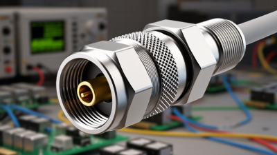
A high-frequency connector carries rapidly changing electrical signals between cables, circuit boards, or test equipment. Its metal center contact carries the signal, while the outer conductor provides a return path and shielding. Together, they form a controlled transmission line. The connector’s geometry and dielectric material help maintain consistent impedance as the signal passes through. Small discontinuities matter. A pin that is slightly misaligned or a poorly seated cable can cause reflections, reducing signal quality.

At high frequencies, engineers examine insertion loss, return loss, and crosstalk rather than relying on continuity alone. IEEE Std 370-2020 sets methods for characterizing interconnects at frequencies up to 50 GHz, using measurements such as scattering parameters. These measurements show how much signal passes through, reflects back, or couples into nearby paths. In practical testing, a network analyzer can reveal a sharp reflection near a connector transition that a basic continuity test would miss. The result depends on the full assembly, not just the connector.

Cable preparation and installation also shape performance. A crushed dielectric or exposed braid can disturb the impedance and weaken shielding. IEC 61169-1 provides general requirements and test methods for radio-frequency connectors, supporting consistent evaluation across designs. Even with careful measurement, real assemblies may behave differently than ideal models. That is easy to underestimate. One connector, cable, or board transition can become the limiting point in an otherwise capable signal path.

How a High-Frequency Connector Transmits Signals

A high-frequency connector carries a rapidly changing electrical signal through a controlled-impedance path. This illustrative 1 GHz sine wave shows normalized signal amplitude over one 1 ns cycle; it is a mathematical waveform, not measured connector-performance data.

Which Design Features Determine Its Performance?

A high frequency connector carries radio-frequency signals between equipment, cables, antennas, and test instruments. It is used in systems where signal quality matters, from wireless communication links to laboratory measurements. At higher frequencies, small geometry changes can affect performance. A connector that seems sturdy may still introduce unwanted reflections.

Its design features determine how cleanly the signal travels. Impedance, often 50 ohms in RF systems, should match the connected cable and equipment. Contact shape, dielectric material, and dimensional tolerances help control reflections and signal loss. Shielding and a consistent outer conductor reduce leakage and interference. Plating and base materials also influence conductivity, durability, and performance across temperature changes. Check the specified frequency range, insertion loss, and return loss for the complete connection—not just the connector alone. Cable quality and installation matter, too. A connector can look perfect and still disappoint if its interface is loose or poorly matched. That detail is easy to overlook.

Tips: Keep interfaces clean and fully seated. Use the recommended tightening method; excessive force can damage delicate contacts. Compare test results at the intended frequency, since performance can vary across the range.

Where Are High-Frequency Connectors Commonly Used?

High-frequency connectors are used wherever signals must travel with low loss, controlled impedance, and limited interference. In wireless infrastructure, they link radios, antennas, filters, and test equipment. A technician might connect coaxial cable to a rooftop antenna, where weather, vibration, and repeated servicing make a secure connection important. Small installation errors matter.

These connectors also appear in radar and satellite systems, laboratory instruments, medical imaging equipment, and high-speed communications hardware. In a test lab, they can link a signal generator to a spectrum analyzer, helping engineers measure frequency response and unwanted reflections. Compact versions may support antenna connections or module testing on circuit boards. The right style depends on the operating frequency, power level, cable dimensions, and equipment layout.

Performance is not automatic. Cable quality, connector wear, contamination, and loose coupling can affect signal measurements. Clean mating surfaces matter. Teams sometimes overlook strain on a cable near the connector; it deserves a second look, especially in portable equipment. Engineers check specifications and test the assembled signal path, since actual results can differ from ideal datasheet conditions.

How Do You Select and Install the Right Connector?

Selecting a high frequency connector starts with the system, not the connector’s advertised maximum frequency. Match its impedance to the transmission line, commonly 50 ohms, then check insertion loss, return loss, and shielding across the actual operating band. IEEE 802.3ck-2022 specifies electrical lanes up to 100 Gb/s, a reminder that tiny discontinuities can matter in fast links. The connector’s frequency rating alone does not guarantee a clean signal.

Check the cable type, board footprint, mating cycles, and expected temperature or vibration. Read the datasheet’s measurement conditions; two loss figures may use different reference planes. Small details matter. During installation, keep connector faces clean, align threads or pins without forcing them, and use the specified torque tool where applicable. A crooked mate can damage contacts or create an unstable connection. Leave enough cable slack to respect its bend radius, and secure the cable so it does not pull on the connector.

After assembly, inspect the interface and verify performance with a calibrated vector network analyzer across the intended band. Compare measured insertion loss and return loss with the design limits, not just a pass light. IEEE 802.3ck’s high-speed requirements are a useful design context, but they do not replace testing the complete cable-and-connector path. I have seen careful parts selection undone by rushed handling; installation deserves the same attention.