Leave Your Message
-
 Email
-
 WeChat

A Pin Header looks simple until the wrong choice causes intermittent contact, assembly delays, or a damaged PCB. A 2.54 mm pitch may suit a development board, while a compact sensor module may need 1.27 mm spacing. Pitch is only one constraint. Current rating, mating height, plating, and mechanical support also affect whether the connection survives actual use. Details matter. Even a correctly spaced connector can fail if its pins barely engage the mating socket.
Signal-integrity expert Eric Bogatin, known for his work on electronic interconnects, uses the phrase “Be the signal.” That perspective is useful when choosing a Pin Header: consider the complete electrical path, including the return connection. For fast signals, pin assignment and nearby ground connections deserve attention alongside connector dimensions. For power connections, check the manufacturer’s current rating and its test conditions, including temperature rise and adjacent loaded contacts. Verify the datasheet. A headline current rating alone may not describe your operating conditions.
This guide examines pitch, pin count, orientation, mounting style, contact finish, and mating compatibility through practical PCB design decisions. A right-angle header can simplify cable routing, yet place extra mechanical stress on solder joints when users disconnect cables. Through-hole mounting may offer useful retention, but assembly requirements still influence the choice. There is no universally correct option, and an inexpensive prototype choice may deserve reconsideration before production. Leave room for doubt. Check the mechanical drawing, confirm the mating pair, and test representative samples under expected operating conditions.
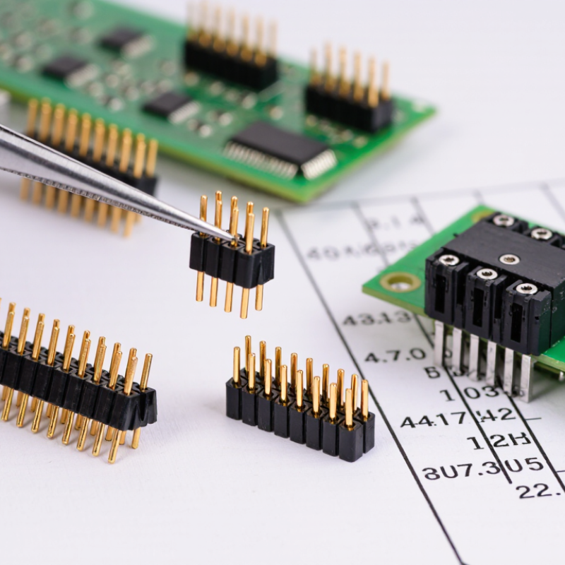
Pin header types shape how a PCB connects to sensors, cables, and other boards. Straight headers suit vertical connections, such as a small sensor board mounted above a controller. Right-angle headers route connections sideways, helping cables clear an enclosure lid. Space disappears quickly. A 2.54 mm pitch is common for prototypes, while 1.27 mm headers allow denser layouts. Smaller spacing also makes manual soldering and probe access harder, especially when nearby components crowd the connector.
Through-hole headers provide mechanical anchoring through soldered pins, making them useful where connections experience occasional handling. Surface-mount headers suit automated assembly and avoid signal-pin holes through the board. However, repeated sideways force can stress their pads unless the connector includes suitable mechanical retention. Check the load path. Single-row headers work well for simple signals and accessible test connections. Double-row versions provide more contacts within a compact footprint, although routing their inner connections can require additional planning.
For removable daughterboards, pair male headers with compatible female sockets and verify the mating dimensions. A matching pitch alone does not guarantee compatibility; pin cross-section, mating depth, and contact geometry also matter. Shrouded headers can guide cable connectors, while keyed versions help prevent reversed insertion when paired correctly. An exposed header may seem adequate until someone reconnects a cable one position off. That tradeoff deserves reconsideration. Before committing the footprint, check the manufacturer's drawing, recommended hole sizes, current rating, and operating temperature against your actual application.
| Pin Header Type | Common Pitch Examples | PCB Mounting | Mating Direction | Key Features | Typical PCB Applications | Selection Considerations |
|---|---|---|---|---|---|---|
| Straight Unshrouded Header | 2.54 mm; 2.00 mm; 1.27 mm | Through-hole or surface-mount versions | Perpendicular to the PCB | Exposed pins; available in single-row and double-row layouts; simple access for sockets and jumper shunts. | Development boards, internal signal connections, programming interfaces, and configuration jumpers. | Check pitch, row spacing, pin cross-section, and mating length. Unshrouded headers generally do not prevent reversed or offset mating. |
| Right-Angle Unshrouded Header | 2.54 mm; 2.00 mm; 1.27 mm | Through-hole or surface-mount versions | Parallel to the PCB | Positions the mating connector beside the board and can reduce the required clearance above the PCB. | Board-edge connections, horizontal cable routing, and connections between perpendicular boards. | Allow space beyond the board edge for the mating connector and cable bend. Check mating forces and solder-joint support. |
| Shrouded Box Header | 2.54 mm; 2.00 mm; 1.27 mm, depending on connector family | Through-hole or surface-mount versions | Perpendicular or parallel to the PCB | A surrounding housing guides mating and protects pins. Many versions provide a polarization feature. | Ribbon-cable connections, internal equipment wiring, and programming or debug interfaces. | Match the mating connector's housing, key position, contact count, and pin numbering. Pitch alone does not establish compatibility. |
| Ejector Header | 2.54 mm; 2.00 mm, depending on connector family | Commonly through-hole; other versions depend on the connector family | Perpendicular or parallel to the PCB | End latches assist connector retention and removal when used with a compatible mating socket. | Serviceable ribbon-cable assemblies, control equipment, and internal connections requiring positive retention. | Reserve space for latch movement and confirm compatibility with the socket body and strain relief. |
| Fine-Pitch Header | 1.27 mm; 1.00 mm | Through-hole or surface-mount versions, depending on connector family | Perpendicular or parallel to the PCB | Provides closer contact spacing for compact layouts. | Compact embedded boards, small modules, and space-constrained programming or debug connections. | Check PCB fabrication and assembly capability, mating alignment, voltage spacing requirements, and the exact contact ratings. |
| Surface-Mount Header | 2.54 mm; 2.00 mm; 1.27 mm; 1.00 mm | Surface-mount solder pads | Perpendicular or parallel to the PCB | Supports reflow assembly and avoids through-holes for signal contacts. Some versions include locating pegs or hold-down tabs. | Automated PCB assembly, compact modules, and boards with dense routing. | Verify the recommended land pattern, coplanarity, reflow profile, and mechanical retention under repeated mating. |
| Extended-Tail Stacking Header | Commonly 2.54 mm; other pitches are available | Typically through-hole | Perpendicular to the PCB | Extended posts can pass through a PCB and engage a mating socket, enabling stacked board assemblies. | Mezzanine boards, expansion boards, and modular embedded assemblies. | Calculate board spacing from the complete mated connector pair. Account for PCB thickness, component height, and required contact engagement. |
| Press-Fit Header | Connector-family dependent; 2.54 mm and 2.00 mm examples exist | Compliant press-fit tails in specified plated through-holes | Perpendicular or parallel to the PCB, depending on design | Creates a solderless PCB termination using a controlled interference fit. | Backplanes, industrial assemblies, and equipment designed for press-fit connector installation. | Follow the specified finished-hole diameter, plating, board thickness, insertion force, and support-tool requirements. Ordinary solder tails are not interchangeable with press-fit tails. |
Pitch and compatibility: Pitch is the center-to-center distance between adjacent contacts in a row. The pitches listed are common examples, not a guarantee that every construction is available at every pitch. Header categories can overlap; a header may be both right-angle and surface-mount.
Electrical selection: Confirm the exact connector's current rating, voltage rating, contact resistance, insulation resistance, and operating temperature. Current capacity depends on contact design, temperature rise, wire size where applicable, and how many contacts carry current simultaneously; pitch alone does not determine it.
Mechanical selection: Match contact count, row spacing, pin dimensions, mating depth, polarization, plating, and the mating socket. Use the recommended PCB footprint and finished-hole dimensions for the selected part.
Application checks: For frequent mating, vibration, or high-speed signals, verify mating-cycle durability, retention, and signal-integrity performance for the complete connector pair.