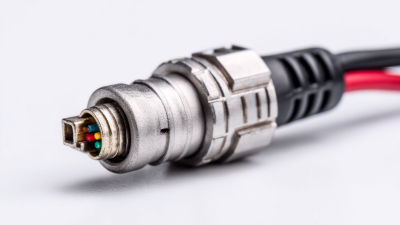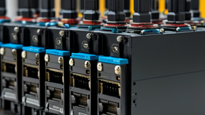


Industrial automation depends on small connections that must perform reliably through vibration, heat, dust, and repeated maintenance. A Plc Connector links controllers with sensors, actuators, communication networks, and power circuits. The right choice can simplify wiring and reduce troubleshooting time. The wrong one may loosen, corrode, or complicate a cabinet upgrade. Small parts matter.
This guide reviews seven PLC connector options for common industrial applications. It considers connection style, contact capacity, wiring method, environmental protection, and compatibility with controller hardware. These details help engineers and technicians compare products beyond appearance or price. A connector suited to a clean control cabinet may not withstand moisture or frequent movement on a production line. Check the manufacturer’s ratings and installation instructions before specifying any part.
There is no universal winner. Each application brings different limits, including available space, cable type, and service access. Even a well-made connector can create problems when installed with the wrong wire size or tool. That point is easy to overlook. The selections ahead offer practical starting points, not a substitute for checking system requirements. Consider how each connector will be installed, inspected, and replaced—not just how it fits on day one.
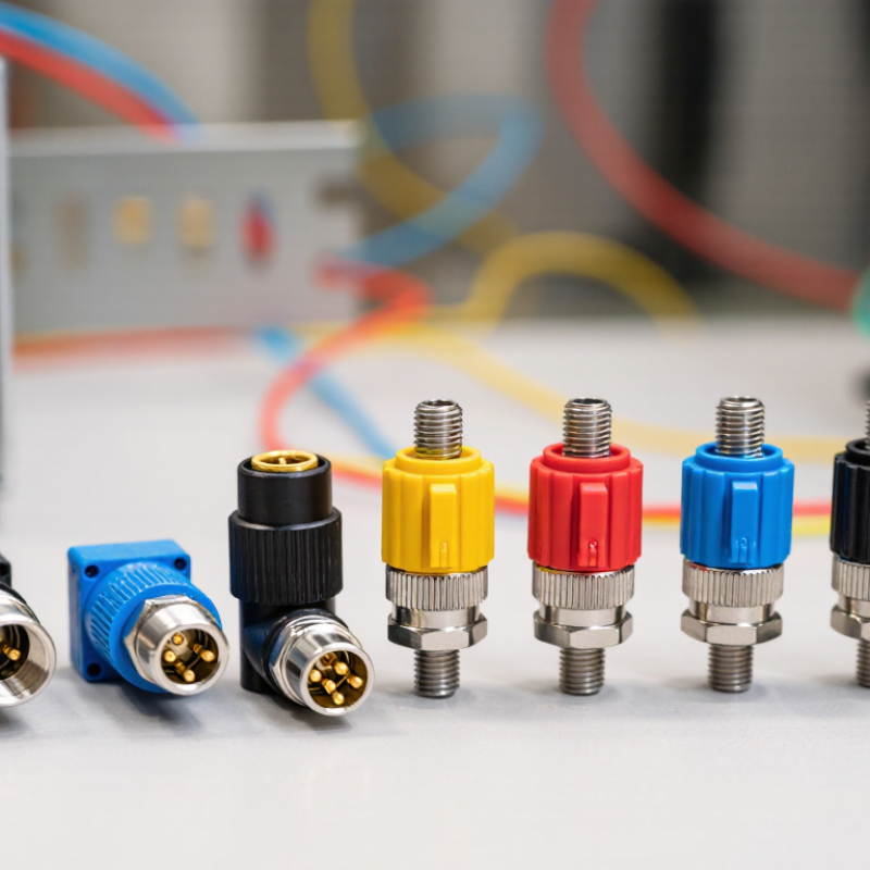
IEC 61131-2 sets requirements and test methods for programmable controller equipment, including its input and output behavior. Connectors help that equipment deliver reliable signals, but the connector alone does not establish compliance. The module, wiring, and installation all matter. A digital input may need a defined voltage range and current to register a clear ON state. Choose terminals and contacts rated for the circuit, and check the I/O module’s specifications rather than relying on appearance.
At the panel, separate low-level sensor wiring from noisy motor circuits where practical. Secure conductors against vibration, label each channel, and use keyed connections when accidental reversal is a concern. These details support dependable operation and make maintenance safer. Small details count. For example, a loose screw terminal can create intermittent readings that disappear during a quick inspection. Connector selection should also reflect the enclosure, temperature, and expected service access. In practice, wiring drawings are not always tidy, so leave room for inspection and retightening. Record the connector type and wiring layout, then verify signals during commissioning under realistic operating conditions. A neat connection helps, but measured performance is what matters.

PLC connections serve three jobs: field I/O, power, and data exchange. Screw-terminal blocks are common for discrete sensors and relay outputs; conductors are secured with a screwdriver. Spring-clamp terminals can speed cabinet wiring and resist vibration, though wire size and ferrule fit still matter. Pluggable terminal blocks let technicians replace an I/O module without disturbing every field wire. That can save time during a fault.
M12 circular connectors often link proximity sensors and actuators to remote I/O. Their threaded couplings help keep connections secure in dusty or wet areas, when the rating is suitable. RJ45 connectors carry Ethernet traffic for controller networks and configuration. Cable routing and shielding deserve care near motor drives. D-sub connectors, such as nine-pin serial types, may still appear on older PLCs or service ports. They are less common in new network designs.
Power needs its own check. M12 L-coded connectors can deliver DC power to distributed equipment; confirm pinout, current rating, and cable compatibility. Space matters. A compact connector may simplify a panel, but leave too little room for a gloved hand or a replacement cable. Connector choice should match the PLC interface, environment, maintenance habits, and electrical load. Even a tidy drawing can miss the awkward bend behind a cabinet door.
In industrial automation, an M12 D-coded connector commonly supports 100 Mbit/s Ethernet links between PLCs, remote I/O, and nearby devices. Its compact, keyed design helps prevent mismatched connections in crowded cabinets and on moving equipment. The coding identifies a connector interface; it does not guarantee the network will reach its rated speed. Cable quality, termination, switch ports, and installation all matter.
For higher data loads, an M12 X-coded connection is designed to support 10 Gbit/s Ethernet. Its eight contacts and internal shielding arrangement help separate signal pairs and reduce interference. That can suit machine-vision cameras or fast data links, provided the cable and connected equipment also support 10 Gbit/s. Check the full channel specification, not just the connector label.
A small detail matters. Keep cables away from noisy power conductors where practical, and avoid tight bends near the connector body. Poor assembly can undermine an otherwise suitable link. Testing after installation can reveal wiring faults or unexpected speed negotiation. Still, field conditions are messy, and a clean test today does not prove every future connection will remain stable. Recheck after maintenance or cable changes.
M12 D-coded connectors support 100 Mbit/s Ethernet, while M12 X-coded connectors support up to 10 Gbit/s Ethernet. These are nominal link rates; actual network throughput depends on the connected equipment and installation.
In industrial automation, an IP67 rating can help protect PLC connectors from dust and temporary immersion. Under IEC 60529, the “6” indicates dust-tight protection, while the “7” covers temporary immersion in water. The familiar reference is up to 1 metre for 30 minutes, under specified test conditions. That detail matters.
A rating is not a promise that a connector can operate underwater. Nor does IP67 automatically cover high-pressure washdown; that requires separate protection testing. Check whether the rating applies when the connector is mated, and follow the specified assembly method. A pinched seal, loose coupling, or damaged cable jacket can compromise protection. Small mistakes matter.
In practice, inspect seals for cuts and grit before installation, then tighten the coupling as instructed. Keep the connector clear of standing water where possible. IEC testing uses controlled conditions, while factory floors bring vibration, temperature changes, and repeated handling. Wear can be easy to miss. IP67 is useful evidence, but it does not replace routine inspection or careful installation.
| Connector Type | Typical Configuration | Common Industrial Use | Key Selection Consideration | IP67 Considerations |
|---|---|---|---|---|
| M12 A-coded | Commonly available with 3, 4, 5, 8, or 12 contacts, depending on the connector design. | Proximity sensors, photoelectric sensors, actuators, and general I/O connections. | Match the contact count, wiring, and coding to the sensor or device; coding helps prevent incompatible connections. | Sealed versions can be rated IP67 when correctly assembled and mated. Verify the rating for the exact connector and cable assembly. |
| M12 D-coded | Typically 4 contacts; commonly used for 100 Mbit/s Industrial Ethernet connections. | Ethernet-connected PLC devices, remote I/O, and industrial network equipment. | Check the device’s supported Ethernet speed, cable category, and network requirements. | IP67 protection is available in sealed designs, but depends on the complete mated connection and installation. |
| M12 X-coded | 8 contacts; designed for high-speed Ethernet, including 10 Gbit/s applications when the entire channel supports it. | High-bandwidth industrial networks and data-intensive automation equipment. | Use compatible X-coded components and suitable cabling; connector coding alone does not guarantee a particular network speed. | Some assemblies are rated IP67 when mated. Confirm the rating and installation conditions in the component documentation. |
| M8 circular | Compact connectors are commonly offered with 3 or 4 contacts; other contact counts are available in some designs. | Compact sensors, actuators, and space-constrained machine installations. | Its smaller form factor can simplify tight layouts, but confirm contact count, current requirements, and cable compatibility. | IP67-rated versions exist. Protection depends on the specific connector, sealing surfaces, and correct mating. |
| 7/8-inch power connector | Commonly used as a circular power connector; contact arrangements vary by design. | Power distribution to field devices, actuators, and certain remote I/O equipment. | Check rated voltage and current, contact arrangement, cable size, and whether the connector is intended for the application’s power circuit. | Sealed variants may provide IP67 protection when properly installed and mated. Do not assume all 7/8-inch connectors have this rating. |
| Sealed industrial RJ45 | Ethernet plug-and-socket connection with an additional sealing and coupling system; contact and performance details depend on the design. | Industrial Ethernet links between PLCs, switches, drives, and networked devices. | Confirm Ethernet category, shielding, cable construction, and compatibility with the device port and sealing system. | IP67 applies only to designs tested and rated as sealed assemblies. An ordinary, unmated RJ45 connection is not inherently IP67. |
| Pluggable terminal block | Removable plug-and-header connection; pole count, pitch, wire range, and termination style vary by product. | PLC I/O wiring, control signals, and cabinet connections that benefit from removable field wiring. | Check voltage and current ratings, conductor size, pitch, retention, and whether the termination is screw, spring, or another specified type. | The terminal block itself does not automatically provide IP67 protection. The enclosure and cable-entry system determine the installed assembly’s ingress protection. |
| IEC 60529 IP67 note: The first digit, 6, means dust-tight; the second digit, 7, denotes protection against temporary immersion under the standard’s specified test conditions. The commonly stated test is immersion in water at a depth of 1 m for 30 minutes, with setup details dependent on enclosure dimensions. IP67 does not by itself establish protection against water jets (IPX6) or continuous submersion. Always check the rating for the complete, correctly assembled connection. | ||||
A PLC connector’s current rating must match the real load, not just the number on a catalog page. Check conductor size, ambient temperature, and neighboring terminals, since heat can reduce safe current capacity. For voltage, compare the rated working voltage with system voltage and likely switching transients. Leave a sensible margin. A connector that barely passes on paper may run hot inside a crowded cabinet.
Vibration and maintenance deserve equal attention. For equipment on pumps or conveyors, look for secure latching and performance tested against IEC 60068-2-6; inspect terminals for looseness during planned service. If washdown is possible, an IP rating gives a defined protection level: IEC 60529’s IPX7 test uses temporary immersion, typically one meter for 30 minutes. That matters. The U.S. Department of Energy’s Operations & Maintenance Best Practices Guide reports predictive maintenance savings of 8–12% over preventive maintenance and 30–40% over reactive maintenance. Those figures are not connector-specific, but they show why easy inspection and replacement can affect operating costs. A rating table still cannot predict every cabinet’s heat, dust, or vibration. Verify the actual installation, and revisit the choice after the first maintenance cycle.