2026 Top Types of Male Header Pins for Global Buyers
In 2026, Male Header Pins remain essential for control boards, industrial sensors, LED systems, and compact consumer electronics. Global buyers now expect more than basic pin counts. They compare pitch, plating, insulation material, current capacity, mating cycles, and delivery stability. A 2.54 mm straight pin header may suit a laboratory controller. A 1.27 mm surface-mount version may fit a dense wearable device. The correct choice depends on the complete assembly, not appearance alone.
Connector specialist Dr. Eric Bogatin offers a useful reminder: “Signal integrity is a system issue, not a connector issue.” His principle matters when buyers select high-speed or closely spaced Male Header Pins. Pin length, ground spacing, solder quality, and PCB layout can change real performance. Buyers should examine straight, right-angle, single-row, dual-row, stackable, shrouded, through-hole, and SMT types. Gold plating can support repeated mating. Tin plating may reduce cost for stable, low-cycle applications. Small details matter.
This guide will compare the top Male Header Pins types for global purchasing teams in 2026. It will discuss practical use cases, material options, customization, packaging, and supplier evaluation. No ranking is universal. That is the difficult part. A low-cost header may fail a vibration test. A premium part may exceed the project budget. Specifications can also look complete while hiding tolerance issues. Careful buyers should request drawings, samples, inspection records, and reliable production evidence before placing large orders. The best selection balances electrical performance, mechanical strength, manufacturing consistency, and total delivered cost.
Male Header Pin Basics: 1.27 mm, 2.00 mm, and 2.54 mm Pitch Standards
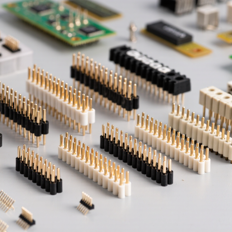
Male header pins are compact connectors used for board-to-board links, cable interfaces, and test fixtures. Their pitch means the center-to-center distance between adjacent pins. The common standards are 1.27 mm, 2.00 mm, and 2.54 mm. Choosing the correct pitch prevents misalignment and assembly delays.
A 1.27 mm header suits dense control boards and compact modules. It saves board space, but inspection becomes harder. A 2.00 mm header offers a practical middle ground for industrial electronics. It provides more clearance than 1.27 mm designs. The 2.54 mm pitch remains widely used for prototypes, educational equipment, and larger control boards. Its spacing makes manual soldering easier. Pin length, plating, insulator height, and contact reliability also deserve attention. A smaller pitch does not automatically mean better performance.
Tips: Confirm the mating socket before ordering. Measure the actual PCB footprint. Check pin count, row spacing, and vertical clearance. Request dimensional drawings and samples for critical projects. I have seen teams select pitch correctly but overlook pin length. That small error can weaken the connection. Also review soldering temperature and surface finish requirements. Tolerance data matters, especially when headers must mate repeatedly. Avoid judging quality from appearance alone. A clean plastic body may still hide poor alignment. Some specifications need questioning. Conditions vary between production lines and applications. Reliability comes from matching the header to the complete assembly, not choosing the smallest available size.
2026 Top Types of Male Header Pins for Global Buyers
Male Header Pin Basics: 1.27 mm, 2.00 mm, and 2.54 mm Pitch Standards
Comparison of widely used male header pin configurations for PCB interconnection and board-to-board applications
| Header Type |
Standard Pitch |
Typical Pin Size |
Common Row Format |
Termination Style |
Typical Applications |
Selection Notes |
| Straight Single-Row Header |
1.27 mm
2.00 mm
2.54 mm |
Approximately 0.40–0.64 mm square, depending on pitch |
1 × N |
Through-hole solder tail or surface-mount tail |
Wire-to-board, PCB modules, programming interfaces, test fixtures |
The most adaptable format; select the pitch and tail length to match PCB layout and mating depth. |
| Straight Dual-Row Header |
1.27 mm
2.00 mm
2.54 mm |
Approximately 0.40–0.64 mm square |
2 × N |
Through-hole or surface-mount |
Board-to-board connections, compact control boards, mezzanine assemblies |
Provides more contacts in a smaller board area than an equivalent single-row design. |
| Right-Angle Header |
1.27 mm
2.00 mm
2.54 mm |
Approximately 0.40–0.64 mm square |
1 × N or 2 × N |
Usually through-hole; SMT versions are also available |
Cable exits, side-entry connections, front-panel interfaces, vertical stacking |
Check the horizontal contact length, vertical height, and cable clearance before ordering. |
| Stackable Header |
2.00 mm
2.54 mm |
Typically 0.50–0.64 mm square |
1 × N or 2 × N |
Extended through-hole pin with mating clearance |
Shield boards, expansion modules, development boards, vertical board stacks |
The extended pin and insulator height must be matched to the required board-to-board spacing. |
| Surface-Mount Male Header |
1.27 mm
2.00 mm
2.54 mm |
Pin dimensions vary by pitch and SMT footprint |
1 × N or 2 × N |
Gull-wing, J-lead, or other SMT-compatible solder tail |
High-density assemblies, automated production, boards without plated through-holes |
Confirm pick-and-place compatibility, coplanarity, pad geometry, and reflow-process limits. |
| Shrouded Male Header |
2.00 mm
2.54 mm |
Typically 0.50–0.64 mm square |
Usually 2 × N |
Through-hole or SMT |
Polarized cable assemblies, keyed board interfaces, embedded control systems |
The surrounding housing helps guide and polarize the mating connector; verify keying and latch geometry. |
| Breakaway Header |
1.27 mm
2.00 mm
2.54 mm |
Typically matched to the selected pitch family |
Single or dual row; separable into custom lengths |
Commonly through-hole |
Prototype boards, low-volume production, custom pin-count layouts |
Breakability and cut-edge quality should be checked when precise end alignment is important. |
Buyer Reference Notes:
Pitch is the center-to-center distance between adjacent pins. The 2.54 mm pitch is widely used in conventional through-hole designs, while 2.00 mm and 1.27 mm pitches support more compact layouts. Actual current rating, mating cycles, plating, insulation height, operating temperature, and dielectric performance depend on the specific construction and applicable test requirements; confirm the component datasheet before final approval.
Single-Row vs. Dual-Row Headers: Density and IEC 60603-13 Compatibility
2026 Top Types of Male Header Pins for Global Buyers
Single-row headers suit simple board connections, service access, and narrow control panels. Their open layout makes each pin easy to probe.
Dual-row headers place contacts closer together, increasing circuit density without expanding the board footprint. That advantage is practical, but it can complicate inspection and rework. In production checks, technicians should verify pitch, pin length, insulation height, and contact alignment with calibrated gauges. A dual-row header is not automatically the better choice.
IEC 60603-13 compatibility requires more than matching a familiar pitch. Buyers should review the applicable dimensional requirements, mating geometry, contact arrangement, and retention features. A header may look interchangeable but still fail during insertion or create unreliable contact pressure.
Confirm drawings, tolerances, plating details, and test reports before approving a global shipment. Regional sourcing can introduce small dimensional differences. Those differences matter.
Tips:
Define the mating connector first. Then compare single-row and dual-row options using the same pitch and current requirements. Check samples under real assembly conditions, including angled insertion and repeated mating. Leave clearance for probes and repair tools. I would also question catalogue wording that says “IEC compatible” without naming the tested dimensions. That phrase sounds useful, yet it may be incomplete.
Straight, Right-Angle, and SMT Headers: PCB Mounting Options for 2026
2026 Top Types of Male Header Pins for Global Buyers
Straight, right-angle, and SMT male headers serve different PCB mounting needs. Straight headers fit vertical connections and support clean, direct board-to-board alignment. They are practical for prototypes, control boards, and cable interfaces. I usually verify pin pitch before reviewing current ratings. A small pitch error can stop assembly.
Right-angle headers route connections along the board surface. They save vertical space and suit side-entry cables, compact enclosures, and stacked PCBs. However, their bent pins need careful mechanical inspection. Uneven insertion depth may create stress during mating. This is easy to miss during a quick visual check. Contact plating, insulation material, and solder-tail length also affect reliability.
SMT headers mount directly onto surface pads and support automated assembly. They work well when through-holes are unavailable or limited. Yet, pad layout must match the component footprint exactly. I have seen good parts fail because the stencil opening was too generous. Placement accuracy, coplanarity, and reflow temperature deserve close attention.
Tips: Confirm pitch, row count, pin length, and mating direction with a physical sample. Check clearance around tall components. Ask for inspection records and material data before volume purchasing. No option is perfect. The best header balances electrical performance, assembly method, space, and service access.
2026 Top Types of Male Header Pins for Global Buyers
Representative nominal contact-pitch options by PCB mounting style. Smaller pitches support higher connector density, while 2.54 mm remains widely used for general-purpose prototyping and control boards.
Straight and right-angle headers are commonly installed through plated PCB holes. SMT headers are placed directly on surface pads and are frequently offered in compact 1.27 mm and 2.00 mm pitch families.
Stamped vs. Machined Contacts: Comparing 1 A, 3 A, and 5 A Ratings
Stamped vs. Machined Contacts: Comparing 1 A, 3 A, and 5 A Ratings
For global buyers, male header pins should match both current demand and assembly conditions. Stamped contacts are formed from metal strip, making them economical for high-volume production. They commonly suit 1 A and moderate 3 A circuits when temperature rise remains controlled. Machined contacts use turned metal, offering stronger dimensional consistency and often better durability. They are useful for 3 A or 5 A applications, especially where repeated mating or stable contact resistance matters. Rated current is not a promise under every condition.
In practical connector selection, I check pitch, pin length, plating, wire temperature, and PCB copper area together. A 5 A rating may require thicker pins, improved heat paths, or current derating in a crowded housing. Stamped pins can perform well, but their edges and spring shape deserve inspection after forming. Machined pins feel more robust, yet they can increase cost and lead time. This trade-off is easy to underestimate. Actual performance still depends on airflow, ambient temperature, mating force, and the complete connector system.
Tips: Ask for test conditions behind every current rating. Compare temperature-rise data at 1 A, 3 A, and 5 A, not only headline specifications. For prototypes, measure contact resistance after repeated mating cycles. A small measurement mistake can change the decision.
Global Compliance Guide: UL 94 V-0, RoHS, REACH, and IEC Requirements
For global buyers, male header pins are not interchangeable. Straight, right-angle, shrouded, and surface-mount types suit different board layouts and mating conditions. Pin pitch, plating, insulator material, and contact retention affect real performance. A cheap sample may look acceptable, yet fail after repeated insertion.
UL 94 V-0 means the tested plastic can self-extinguish within defined limits. It does not certify the complete header assembly or the final device. Ask for the material grade, test reference, and supporting report. RoHS compliance requires control of restricted substances, including lead, mercury, and certain flame retardants. REACH requires careful review of substances of very high concern and related communication duties. Request a current declaration, not an old website statement.
IEC requirements depend on the header design and application. Relevant IEC 60603 connector specifications and IEC 60512 test methods may address dimensions, electrical performance, endurance, or mechanical strength. Confirm the exact standard edition and product scope. During sourcing, inspect samples under magnification, measure pitch with calibrated tools, and compare plating thickness with the specification. Keep lot numbers and supplier records.
One detail is often missed. V-0, RoHS, REACH, and IEC evidence may come from different documents. They must still describe the same material and product family. This is where reviews become imperfect. A declaration can be complete but outdated. Recheck before production.

 Email
 WeChat