


Custom connectors are common in high-performance systems
Designers often try to use standard interconnects in their final products. Most people cite usability to explain why they stick with standard off-the-shelf products. Sometimes, however, no standard product exists that meets the system design requirements and a custom or modified interconnect is chosen.
The use of non-standard connectors is more common than most designers think. For example, about 25% of Samtec's sales are non-standard products, ranging from minor modifications of existing products to completely new connector systems. These products include high-speed board-to-board (sandwich) systems, high-speed cable assemblies, backplane panels and cable systems, two-piece pin and socket systems, active cable assemblies (referred to as "mid-board optical transceivers" in Samtec's new optical guide), and RF connectors and cable assemblies.
Designers of high-speed systems (112 Gb/s data rate per channel PAM4, 224 forthcoming) such as data centers, supercomputers, automated test equipment, and medical imaging often use high-speed cable assemblies to transfer large amounts of data at high data rates.
Although there are a variety of standard high-speed cable assemblies, many customers specify modifications to these standard products. Common modifications include custom PCB designs for pin mapping for specific applications, placing protective bushings around low-deflection twin-core cables, or adding labels tO Connectors and cables to identify part numbers or provide instructions, to name just a few of the hundreds of potential modifications that can be made.
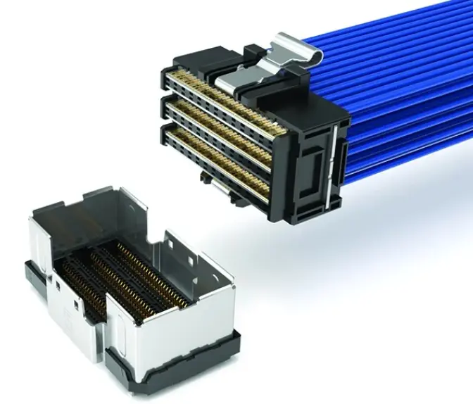
Another popular modification is to mix and match the end 1 and end 2 connectors of the component. For example, the Flyover® QSFP-DD front panel connector can be terminated to any number of high-density end-2 connectors placed near the chip. Designers require various types of connectors for front, middle, and rear panel interconnect systems.
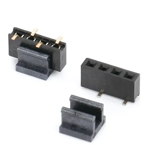
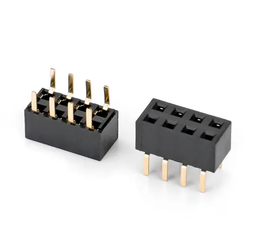
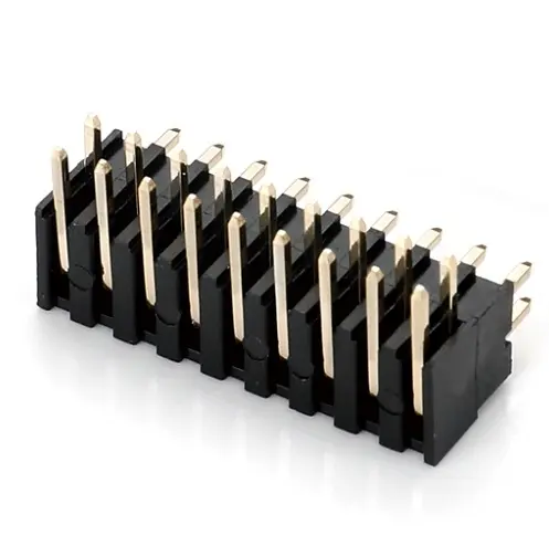
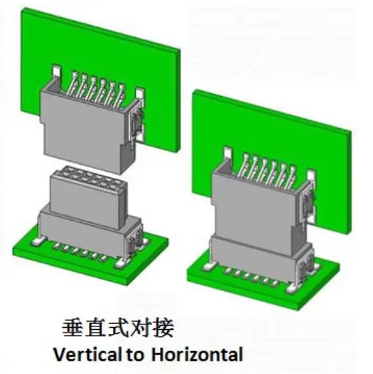
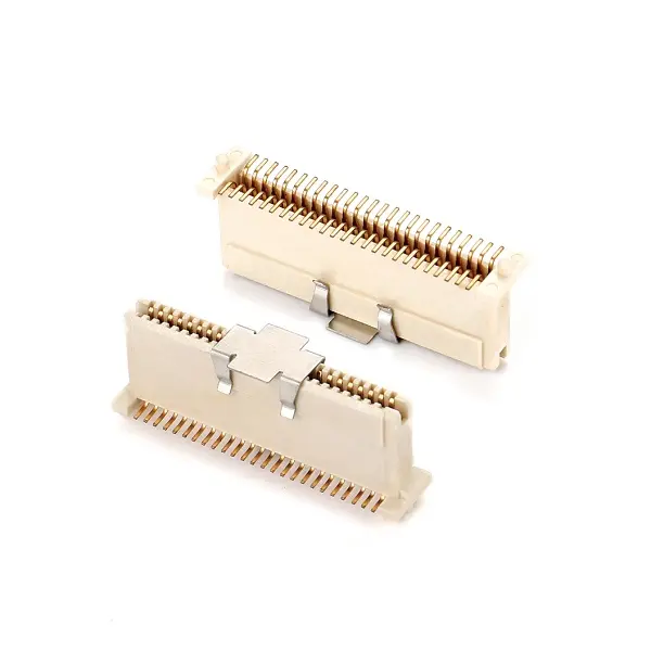
Cutting-edge high-speed systems require the next generation of high-performance connectors. However, many manufacturers are designing for more "direct" applications such as industrial automation, robotics, embedded products, and vision and security systems. These boxes often use more basic traditional interconnects, such as square post terminals (" connectors ") and socket boards. The relatively simple design of these products - strip line plastic insulators and non-miniature centerlines (e.g., 2.54 or 2.00mm with 1.00 or 0.80mm pitch) - makes modifications simple and relatively quick, and therefore inexpensive.
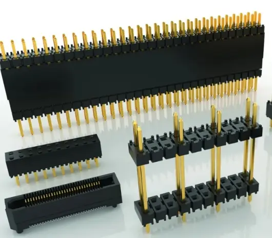
Popular modifications include multi-pin polarization - removing pins - to allow keying, airflow, signal mapping, and additional space for power transmission or creepage distance and clearance to meet safety and regulatory standards. Most designers using board level connectors are trying to meet UL and CE 61800-5-1 specifications, which specify creepage distance and clearance distance for a given material grade, operating voltage, and contamination level.
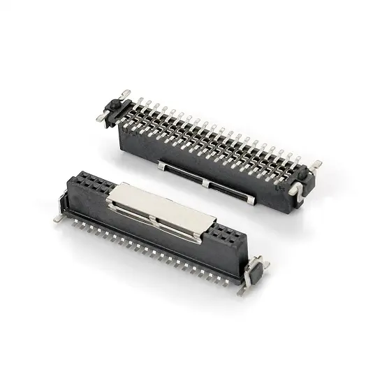
Another popular modification is the addition of alignment and polarization features such as shield, import, and blind plug support, as well as the combination of power and signal pins into a single connector. Combining power and signal pins into a single connector system saves PCB space and improves tolerances for matching connector groups.
Most board-to-board connectors have a carefully designed signal-to-ground configuration to achieve SI (signal integrity) performance, which requires low mode conversion to reduce radiated noise or sensitivity to noise. If additional shielding performance is required, the connector can be encapsulated in an external metal shield that wraps around the entire Mating Connector system to minimize EMI and EMC effects.
Electroplating is another common modification; This includes heavy gold, silver and palladium nickel, among others. Most designers aim for higher cycles, protection against harsh environments, shock and vibration, and higher operating temperatures.
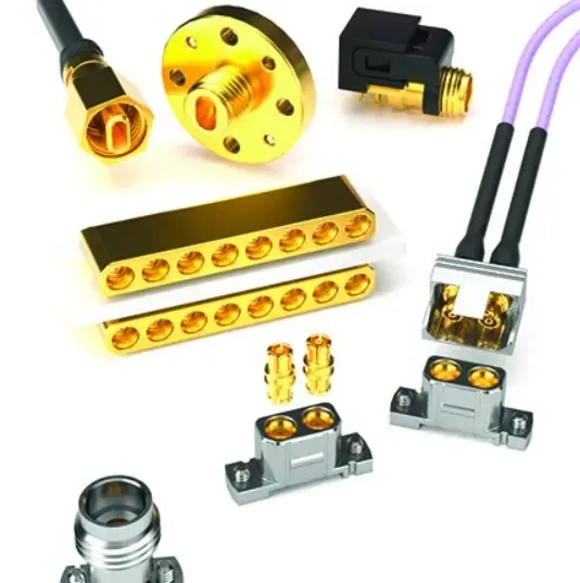
RF connectors and cable assemblies are frequently modified. Common requirements include linkage connectors located on tighter centerlines or with an odd number of pins. Designers often require our linkage RF connectors, such as MagnumRF™ or Bullseye® test point systems, to have specific position counts, spacing, and custom layouts. This may allow them to reduce the length of the wiring or fit the connector into a limited space on the PCB, allowing the connector to be placed closer to the chip. Phase-matched wiring and labeling are also common RF modifications.
All of the examples cited above are modifications to existing connectors. Some systems require entirely new connectors, which may include custom pins and stamping parts, plastic insulators and housings, custom RF, metal, special packages, custom housings and packages, and more. Work closely with your connector supplier to create the ideal interconnect solution to maximize system performance.