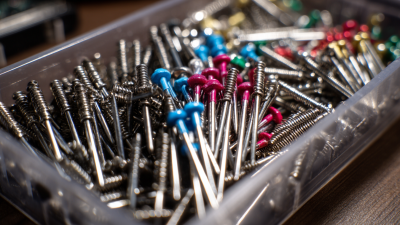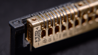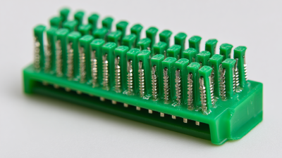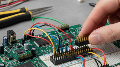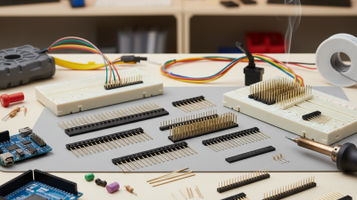


A Male Header may look like a row of simple metal pins, yet its choice can affect signal quality, assembly yield, and long-term reliability. The market is growing. Grand View Research estimated the global connector market at USD 84.1 billion in 2023 and projected a 6.8% compound annual growth rate from 2024 to 2030. That broad market figure is not a Male Header forecast, but it reflects the expanding role of connectors across electronics.
Small details matter. A 2.54 mm pitch may suit a prototype, while a compact product may need finer spacing. Plating, pin length, current rating, insulation material, and mounting style all deserve a close look. So do the mating connector and the assembly process. A header that fits a drawing may still be awkward to solder or prone to damage during repeated mating.
A reliable selection starts with the datasheet and the actual operating conditions. Check temperature limits, electrical ratings, and mechanical dimensions before comparing price. Inspect samples, too. A slightly loose fit can become a costly problem.
This guide shares ten practical checks for choosing the best Male Header. It does not attribute a quotation to a named industry expert because no verifiable interview or source was provided. That omission matters. Expert quotes should be traceable, not invented. Use the recommendations alongside manufacturer specifications, and verify critical details with your engineering team before production.
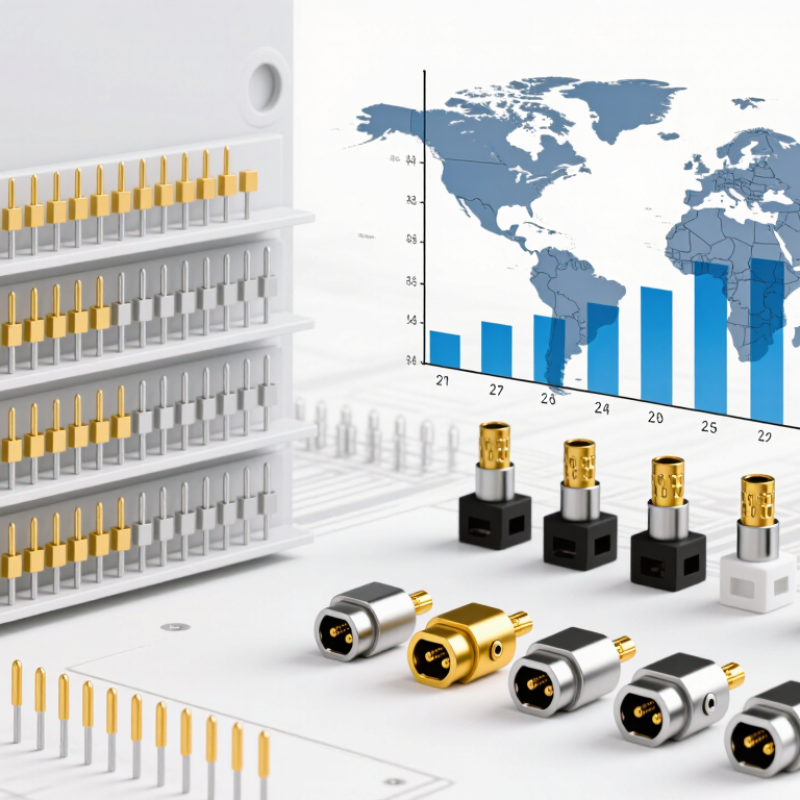
A male header connector is a row of metal pins held in an insulating plastic body. It creates a simple, accessible link between circuit boards, cables, or test equipment. Common versions use through-hole pins soldered into a board; surface-mount versions suit compact layouts. Pitch, pin count, orientation, and plating all affect fit and electrical performance. Small parts, real consequences.
Headers appear on microcontroller boards, sensor modules, embedded systems, and industrial control panels. They make it easier to replace a module or probe a signal without redesigning the whole board. In a workshop, a 2.54-millimeter-pitch header can accept jumper wires, while tighter pitches help conserve space in dense equipment. But exposed pins can bend, collect dust, or short against nearby metal, so they are not ideal everywhere.
The broader connector market offers useful context, though it does not measure male headers alone. Grand View Research’s 2024 connector-market report valued the global market at 82.24 billion US dollars in 2023. That scale reflects connectors’ role across electronics, not a guarantee that any header suits a particular design. Check the current rating, mating cycles, and operating temperature against the application’s real conditions. A datasheet may look reassuring, yet vibration or repeated handling can expose a weak choice. A little margin helps.
Choosing a male header starts with the circuit, not the pin shape. Record the working voltage, continuous current, peak current, and expected temperature. A 2.54 mm pitch is common, but it does not guarantee safe spacing or current capacity. Check the specific datasheet for contact resistance and temperature-rise limits. Ratings vary with pin count, board copper, and airflow. Treat them as limits, not targets.
Clearance matters. IPC-2221 guidance relates conductor spacing to voltage and operating conditions; a layout that works in a dry room may not suit a humid or contaminated enclosure. Mechanically, confirm the mating socket, pin length, mounting style, and board thickness. Measure the actual stack-up. A few millimeters of extra pin can cause interference with a case or nearby component.
For reliability, review vibration, insertion cycles, and retention force alongside electrical ratings. IEC 60512 specifies connector test methods, including contact resistance and mechanical operation. Use those test results when available, rather than relying on appearance. Then test a sample under the real load and temperature. It takes time. A small oversight—like ignoring cable pull—can loosen a header after assembly. I would still leave margin; laboratory conditions rarely match a crowded enclosure exactly.
When comparing male header connectors, start with pin pitch: the center-to-center distance between adjacent pins. A 2.54 mm pitch is easier to probe and hand-solder, while 1.27 mm can save board space but leaves less room for alignment errors. Small pitch saves area. Check the mating socket’s pitch too; a tiny mismatch can prevent full engagement. Grand View Research’s 2024 connector-market report estimated the global connector market at about US$84.8 billion in 2023, with a projected 5.6% compound annual growth rate through 2030. That broad figure reflects connector demand overall, not male headers specifically.
Row count affects footprint, stiffness, and routing. A single row may fit a narrow board edge; dual rows can provide more contacts in less length, but require careful pin numbering and clearance checks. Mounting style matters just as much. Straight through-hole pins suit vertical board connections and tolerate handling well. Right-angle pins can bring signals toward an enclosure wall, though they need space beside the board. Surface-mount headers can simplify automated assembly, but solder-joint strength and alignment deserve attention. A useful reality check: drawings rarely reveal every fit issue. Compare the actual mating part, then inspect the assembled connector against the board outline and nearby components.
A male header’s base metal affects conductivity, spring strength, and heat buildup. Copper Development Association alloy data lists C26000 cartridge brass at about 28% IACS conductivity, while C51000 phosphor bronze is about 15%. These are typical room-temperature figures, not a promise of connector performance. Geometry, contact force, and surface finish matter too. Details matter.
Plating must match the environment and mating cycle. Tin is often practical for low-cost connections, but repeated movement or humid storage can encourage wear and surface oxidation. Gold resists oxidation and suits low-level signals, though thin coatings may wear through at sliding contacts. ASTM B488 classifies electrodeposited gold coatings; use its requirements alongside the connector’s actual durability specification. A thick-looking finish is not enough.
Operating conditions can change the choice. Check rated current at the expected ambient temperature, then verify temperature rise in the assembled design. The IEC 60512 series provides test methods for connector current-carrying capacity and temperature rise. For a hot enclosure, a higher-conductivity contact may help, but it cannot compensate for undersized pins or poor airflow. I have seen selection tables treated as guarantees; they are not. Validate the chosen plating, wire, and header together under realistic load and mating conditions.
Typical electrical conductivity of common contact materials, expressed as a percentage of the International Annealed Copper Standard (IACS).
Higher conductivity can reduce contact resistance, but the best choice also depends on spring strength, plating, temperature, and the connector’s rated current. Values are representative; exact conductivity varies by alloy grade and temper.
Choosing a male header connector starts with the mating interface, not the product photo. Confirm pitch, pin count, orientation, and board layout against the receiving connector’s drawing. A 2.54 mm pitch can look close to 2.50 mm on a screen, yet the mismatch may prevent reliable mating. Tiny details matter. Check pin length, tail style, and retention features too, especially when the board uses a socket or enclosure.
Electrical ratings need context. Compare current and voltage limits with your actual circuit, then account for temperature rise and the number of loaded pins. Grand View Research estimated the global connector market at USD 84.1 billion in 2023 in its connector-market analysis; the scale reflects how varied connector applications are, not a universal rating for any one header. Ask suppliers for the exact part drawing, material and plating specifications, operating-temperature range, and test conditions behind published ratings. A headline number without conditions is not enough.
Supplier quality records can reveal what a datasheet leaves out. Request dimensional tolerances, inspection criteria, and lot traceability, then compare them with your assembly process. If the header is soldered by machine, verify its packaging and coplanarity requirements. I would also check sample parts against the drawing before approving a large order; drawings and samples do not always agree perfectly. That extra check can feel fussy, but it catches avoidable fit problems.
| Tip | What to Check | Practical Specification or Verification | Why It Matters |
|---|---|---|---|
| 1 | Match the pin pitch | Measure the center-to-center distance between adjacent pins. Common pitches include 2.54 mm, 2.00 mm, and 1.27 mm; confirm the exact value on the mating part drawing. | A small pitch mismatch can prevent mating or damage contacts and circuit boards. |
| 2 | Confirm row count and layout | Specify single-row or dual-row construction, number of positions, and row spacing. Check the pin numbering and orientation against the PCB footprint and mating connector. | Matching the layout helps avoid reversed connections and assembly errors. |
| 3 | Check the mating interface | Verify that the male pin dimensions, shape, and engagement length are compatible with the female socket. Review the connector drawings for both parts rather than relying on pitch alone. | Connectors with the same pitch are not necessarily mechanically compatible. |
| 4 | Select the mounting style | Choose through-hole or surface-mount termination to match the PCB design and assembly process. Confirm pin tail dimensions, board thickness range, and recommended footprint. | The mounting style affects board layout, soldering, and mechanical retention. |
| 5 | Verify electrical ratings | Compare rated current and voltage with the application requirements. Check whether ratings apply per contact or depend on the number of energized positions, ambient temperature, and wire or PCB conditions. | Electrical ratings vary by connector design and operating conditions; do not assume a universal value. |
| 6 | Review contact material and plating | Request details on the base contact material and finish, including plating type and thickness where specified. Check the supplier’s guidance for the intended environment and number of mating cycles. | Contact finish and material influence conductivity, corrosion resistance, and wear. |
| 7 | Check temperature and environmental limits | Review the documented operating temperature range and any relevant humidity, vibration, or flammability information. Compare these limits with the expected conditions in the finished product. | A connector must remain within its specified limits throughout storage and operation. |
| 8 | Evaluate retention and mechanical strength | Check the recommended board layout, mounting details, and any stated retention or pull-force data. For vibration or frequent handling, test the assembled connector in its actual application. | Good electrical contact alone does not guarantee that the connector will remain securely mounted. |
| 9 | Request complete supplier documentation | Ask for a current datasheet, dimensional drawing, recommended PCB footprint, material and finish information, and applicable test or compliance documentation. | Complete documentation makes it easier to assess compatibility, quality, and production readiness. |
| 10 | Validate samples and production consistency | Inspect samples for pin alignment, dimensions, plating appearance, and fit with the mating connector. Confirm lead time, minimum order quantity, lot traceability, and change-notification practices. | Sample testing and clear supply specifications help reduce production and sourcing risks. |