How to Choose the Right Pin Header Socket for Your Electronics Project
Choosing the right Pin Header Socket for your electronics project can significantly impact the functionality and reliability of your design. As John Smith, a leading expert in connector technologies, aptly stated, “The right socket can make or break the connection in any circuit.” This underscores the importance of selecting the appropriate Pin Header Socket to ensure optimal performance and compatibility in your electronic designs.
When embarking on your project, it’s essential to consider various factors such as pin count, pitch, and mounting style. Each of these elements plays a crucial role in the overall layout and efficiency of your electronic system. A well-chosen Pin Header Socket not only facilitates seamless connectivity but also enhances the longevity of your components, making it a vital consideration for both hobbyists and professionals alike.
In an era where electronics are becoming increasingly intricate, understanding the nuances of Pin Header Socket selection can lead to better project outcomes. By focusing on the attributes that align with your specific needs, you can elevate your electronics project from ordinary to extraordinary, ensuring that every connection serves its intended purpose.
Understanding the Basics of Pin Header Sockets in Electronics
Pin header sockets are essential components in the world of electronics, serving as a means to establish a secure and reliable connection between printed circuit boards (PCBs) and various components. These sockets consist of a series of metal pins arranged in a row, allowing for easy insertion and removal of connectors. Understanding the basics of pin header sockets can significantly simplify the design and assembly process of your electronics projects.
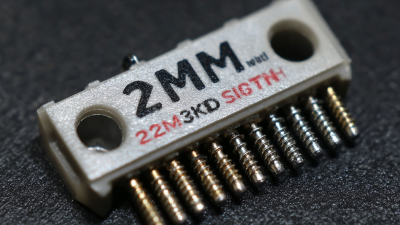
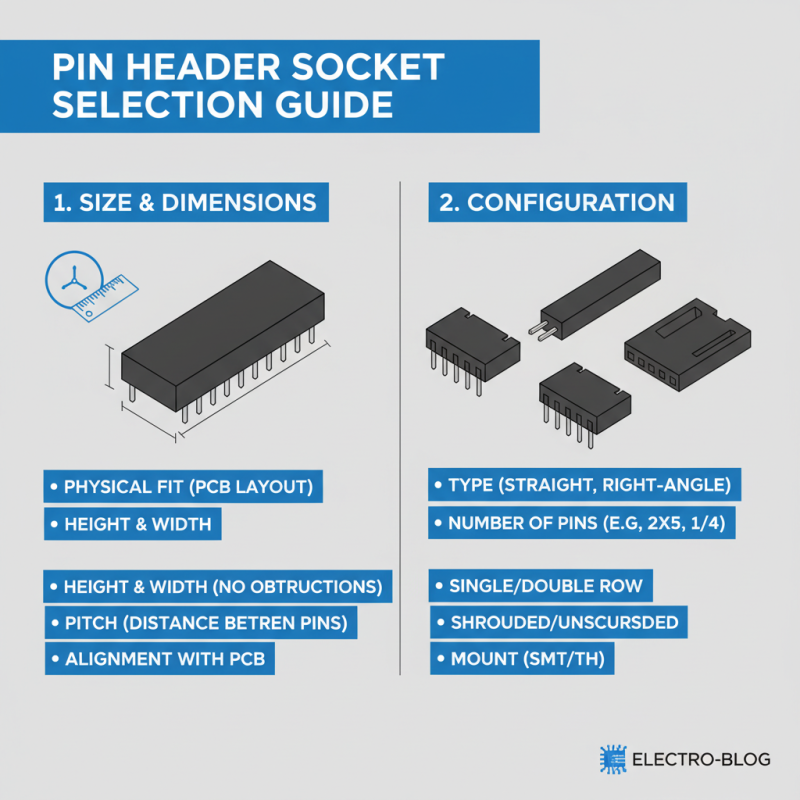
When selecting the right pin header socket, consider factors such as pin spacing, pin count, and mounting style. Pin spacing, commonly measured in millimeters, affects compatibility with various connectors. Standard spacing includes 2.54mm, which is widely used in many applications. Additionally, the number of pins required will depend on your specific project needs, influencing both the size and layout of your PCB. Mounting styles, including through-hole and surface mount, also play a crucial role in determining how the socket integrates into your design, impacting durability and ease of use.
Finally, it’s important to consider the electrical ratings and material properties of the pin header sockets. Different applications may require sockets that can handle varying levels of current and voltage. Additionally, factors like temperature tolerance and corrosion resistance should be evaluated based on the environment in which the electronics will operate. By delving into these fundamental aspects, you can ensure a proper selection that meets the requirements of your electronics projects.
Identifying Your Project's Requirements for Pin Header Sockets
When selecting the right pin header socket for your electronics project, understanding your project's specific requirements is crucial. Begin by considering the number of pins you need. Assess the configuration of your circuit and determine whether you require single-row or double-row pin headers. This choice not only impacts the physical space on your board but also the wiring complexity and component accessibility in your design.
Next, evaluate the pitch of the pin header socket, which refers to the distance between pin centers. Common pitches include 2.54mm (0.1 inch) and 2.0mm, among others. Make sure to match the pitch with your circuit design specifications to ensure compatibility with other components. Additionally, think about the current and voltage ratings necessary for your application. Selecting a pin header that can handle the required electrical specifications will help prevent failure and ensure reliable performance in your project.
Types of Pin Header Sockets: Which One Is Right for You?
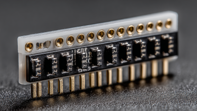
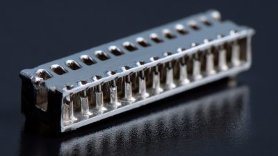
When embarking on an electronics project, selecting the right pin header socket is crucial for ensuring effective connections. There are several types of pin header sockets available, each serving different purposes. The most common ones include standard, low-profile, and insulated pin headers. Standard pin headers are widely used due to their versatility, while low-profile variants are ideal for compact designs where space is limited. Insulated pin headers come with a plastic housing that prevents short circuits and enhances circuit reliability.
When considering which pin header socket is right for your project, it's important to assess your specific needs. For instance, if you anticipate needing to make frequent connections and disconnections, opt for sockets with a higher insertion and extraction life. Additionally, pay attention to the pin spacing; standard spacing is typically 2.54mm, but other sizes may be better suited for specialized applications.
Tips: Always verify the current and voltage ratings of the socket to guarantee compatibility with your circuit. Consider the environmental factors as well, since some materials may not perform well in high temperatures or humidity. Finally, test the socket with a prototype to confirm that it meets your project requirements before final assembly. Choosing the correct pin header socket can significantly impact the overall performance and longevity of your electronics project.
How to Choose the Right Pin Header Socket for Your Electronics Project
| Type of Pin Header Socket |
Number of Pins |
Pin Spacing (mm) |
Orientation |
Common Applications |
| Standard Pin Header |
2 to 40 |
2.54 |
Vertical |
General electronic connections |
| Right Angle Pin Header |
2 to 16 |
2.54 |
Right Angle |
Compact designs |
| Double Row Pin Header |
2 to 64 |
2.54 |
Vertical |
Microcontrollers and PCBs |
| High-Current Pin Header |
2 to 40 |
3.96 |
Vertical |
Power applications |
| SMD Pin Header |
2 to 20 |
1.27 |
Surface Mount |
Compact and low-profile designs |
Evaluating Size and Configuration Options for Pin Header Sockets
When selecting a pin header socket for your electronics project, size and configuration are crucial factors to consider. First, it's essential to assess the physical dimensions of the socket required for your application. Pin headers typically come in various heights and widths to accommodate different PCB layouts. Ensure that the socket fits the available space on your circuit board without obstructing other components or functionalities. Measuring the pitch, or the distance between the pins, is vital as it must align precisely with the corresponding pin layout on your PCB for effective connectivity.
In addition to size, evaluating the configuration options of pin header sockets can have a significant impact on the overall design of your project. Standard configurations include single and dual-row arrangements, which influence how easily connections can be made and how much space they occupy. It's also essential to consider whether you need straight or right-angle pins, as this choice affects the orientation of cable connections and the accessibility of the header. Furthermore, if your project demands a more robust solution, look into locking mechanisms or retainers to secure the connection and prevent accidental disconnections during operation.
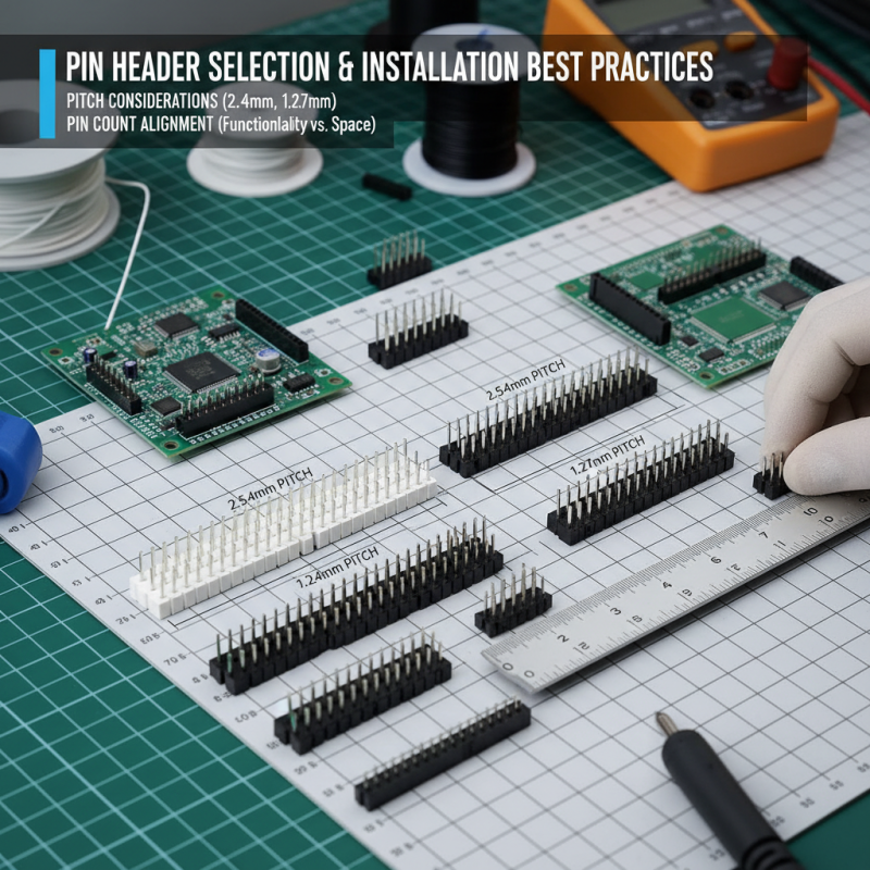
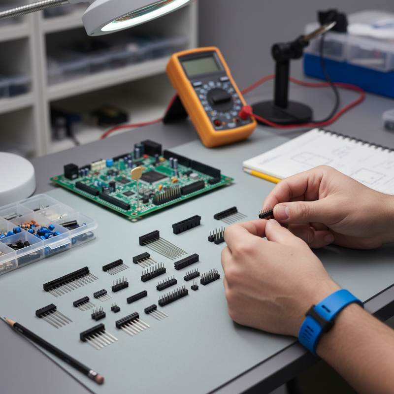
Best Practices for Selecting and Installing Pin Header Sockets
When selecting and installing pin header sockets for your electronics project, several best practices can greatly enhance performance and reliability. First and foremost, it is crucial to consider the pitch of the pin header socket, which is the distance between the individual pins. Common pitches are 2.54mm and 1.27mm, and selecting the appropriate pitch ensures a secure and compatible connection with your circuit board layout. Additionally, take into account the number of pins required; this should align with the specific needs of your project, balancing functionality with space constraints.
Installation techniques also play a vital role in the effectiveness of pin header sockets. Ensure that you insert the pins straight into the socket to avoid bending, which can lead to poor connections and potential failures. A soldering iron with a fine tip is recommended for more precise application, allowing you to control the amount of solder used, which prevents cold solder joints. Furthermore, employing a heat sink during soldering can help protect the socket from heat damage. Finally, always verify your connections through visual inspection or functional testing before finalizing your project to catch any errors early on.

 Email
Email WeChat